
ZGS type combined transformer
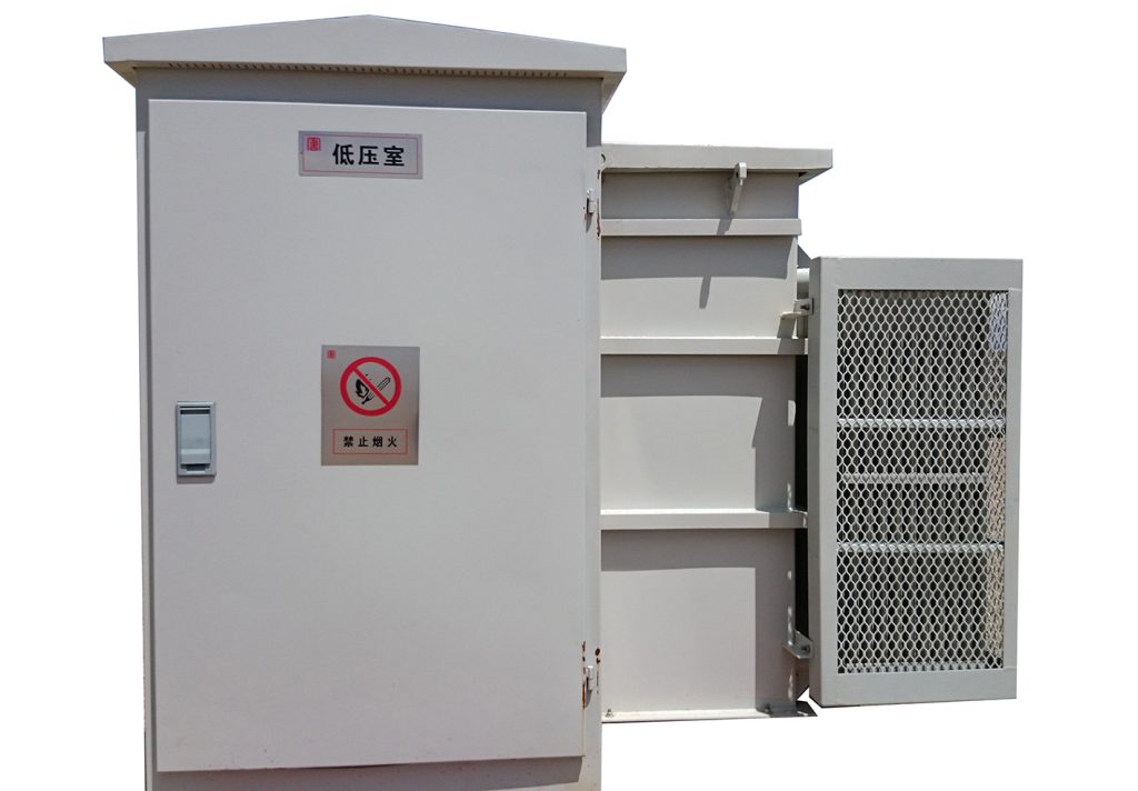
The combined transformer (also known as the American-style substation, hereinafter referred to as “American transformer”) is a series of products independently developed by our company by digesting and absorbing advanced domestic and foreign technologies. This product utilizes high-tech intelligent control technology, installing the transformer, load switch, and high-voltage fuse inside the transformer tank. The transformer insulation serves as the insulation and heat dissipation medium for the entire product. It features small size, light weight, convenient installation and maintenance, high safety and reliability, and an attractive appearance.
■Structural Features
- The product consists of three parts: transformer, high-voltage system, and low-voltage system.
- The transformer performance conforms to the S11 type transformer technical performance. American-made transformers with S13 and SH15 technical performance can be provided upon request.
- The high-voltage side uses a V-type or T-type load switch with two-stage fuse protection. A current-limiting circuit breaker is used for line protection. The fuse capacity is large. A plug-in circuit breaker is used to protect the transformer’s secondary side from overload and short circuit.
- The load switch and fuses are installed inside the transformer tank, utilizing the transformer’s insulating oil as the insulating and heat dissipation medium.
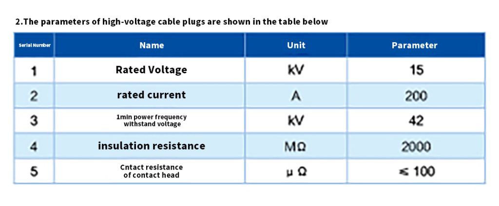
- The high-voltage side incoming line uses a high-voltage cable plug, and the high-voltage compartment is fully insulated.
- Standard products use direct low-voltage outgoing lines. Low-voltage metering and branch outgoing lines can be added upon request.
- The tank is constructed of welded steel plates with corrugated sheets for three-sided heat dissipation and a gold-sealed structure. It undergoes special processing, resulting in strong corrosion resistance and an aesthetically pleasing appearance.
- The high-voltage and low-voltage compartments are separated. Operable components in the high-voltage compartment include: load switch, transformer tap changer, high-voltage incoming line connector, and plug-in fuse.
- The enclosure contains: oil level thermometer, oil level gauge, pressure relief valve, drain valve, oil sample valve, low-voltage outgoing line terminals, and a low-voltage gauge system configured according to user requirements.
■Use Conditions
- High ambient temperature: +40℃, Low ambient temperature: -25℃
- Altitude: <1000m
- High monthly average relative humidity: 90% (20℃)
- Outdoor wind speed not exceeding 35 ml/s
- Installation location: Install in areas free from fire, explosion hazards, severe pollution, chemical corrosion, and violent vibrations.
■Applications
This transformer is used in 10/0.4kV, 50Hz power distribution systems. The rated capacity of the transformer is 50-1600kVA. It is widely applicable to urban areas, residential communities, mines, hotels, hospitals, parks, oil fields, airports, docks, railways, temporary facilities, outdoor explosion sites, and other power consumption locations. It can be used in ring network power distribution systems and as the terminal power supply for radial power grids. Severe earthquake
■Installation dimensions and foundation
The external dimensions will vary depending on the low-voltage side scheme. Generally, the customer will be notified one month prior to delivery.
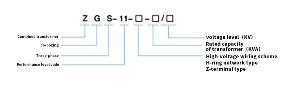
■Model description
■Installation, Use, and Maintenance
- A grounding wire should be pre-buried before installation, with a grounding resistance value not exceeding 4 ohms.
- Upon receiving the product, the user should check the received model and specifications against the nameplate to ensure they match the contract. The user should also check the technical documents against the packing list to ensure they are complete. Products not intended for installation should be stored under normal operating conditions. After normal transportation, this series of transformers does not require core lifting inspection. Removable components can be installed, and test runs can be conducted. Once qualified, it can be put into operation.
- When lifting, the angle between the wire rope and the plumb line should be less than 20 degrees. The inclination during product transportation should not exceed 15 degrees. Lift and lower the transformer gently.
- Seal the connection between the transformer bottom and the foundation with cement to prevent foreign objects from entering.
- Before commissioning, check that the insertion-type tube is installed correctly, the high-voltage plug connection is reliable, and the transformer’s branch switches are in the correct positions. 6. Load switch operation: The load switch should rotate smoothly. Check the reliability of all connections and ensure the grounding bolts on the reinforcing bars are tightened. 7. Fuse usage and replacement: The backup current limiter is installed on the upper part of the transformer tank and immersed in oil. When replacing it, disconnect the load switch, unplug the high-voltage plug, and ensure the entire product is in a dry isolation state. Open the tank cover to replace the fuse. Before removing the overload protection fuse, disconnect the load switch to release the pressure in the tank before proceeding with the operation. Use the operating lever during operation.
- Load switch operation: The load switch is a three-phase interlocking switch with a spring operating mechanism, fully compliant with opening and closing operations. There are two types of load switches, one for ring network power supply systems and the other for radial terminal power supply systems. Load switches for ring network power supply systems are four-position load switches. Load switches for terminal power supply systems are two-position load switches, capable of opening and closing the transformer. Load switch operation steps: The load switch can be rotated clockwise or counterclockwise. Each rotation of 100 degrees represents one position. First, determine the location of the load switch, then determine the desired operating position based on the circuit. Use the operating lever to rotate the switch to the required position to complete the operation. Note: The load switch cannot be switched when the transformer uses hard oil.
- Maintenance: After a fuse blows, the cause of the fault should be checked promptly. When replacing the fuse, the fuse model should be selected according to regulations. For safety, the operating lever must be used during live operation.
■ Ordering Instructions
When ordering, the ordering party should provide the following data related to the product:
- Product Model:
- Transformer Capacity:
- Transformer Oil (Ordinary Oil, High Flash Point Oil, Silicone Oil)
- High and Low Voltage Side Wiring Scheme and Selection of Electrical Components and Parameters:
- Housing Color
- Required Spare Parts
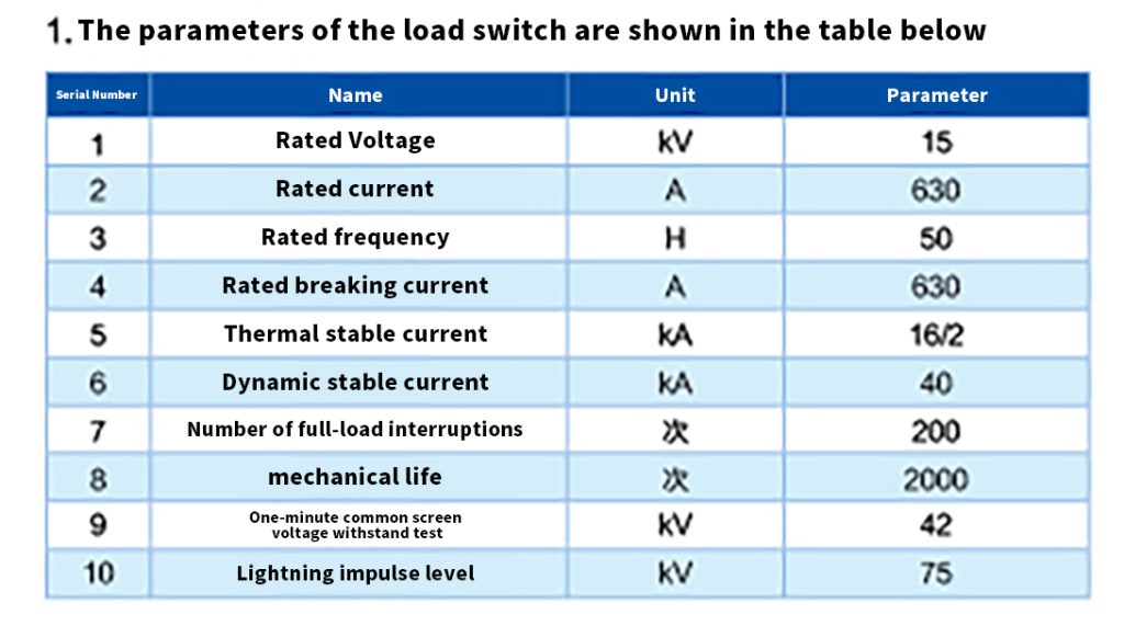
■ Technical Parameters
- Fuses
The backup current fuse and plug-in torch fuse are oil-filled.
Transformer Connection Method and High-Voltage Tap Range:
The transformer connection method is Yy nO or Dyn ll, and the tap range is ±5% ±2 x 2.5%, or as specified by the user in the technical agreement. Any range exceeding the above technical parameters can be resolved through negotiation with our company.
Accompanying Documents and Accessories
The product comes with a packing list, certificate of conformity, factory test report, installation and operation manual, electrical schematic diagram, secondary wiring diagram, keys, and various spare parts provided according to the agreement.